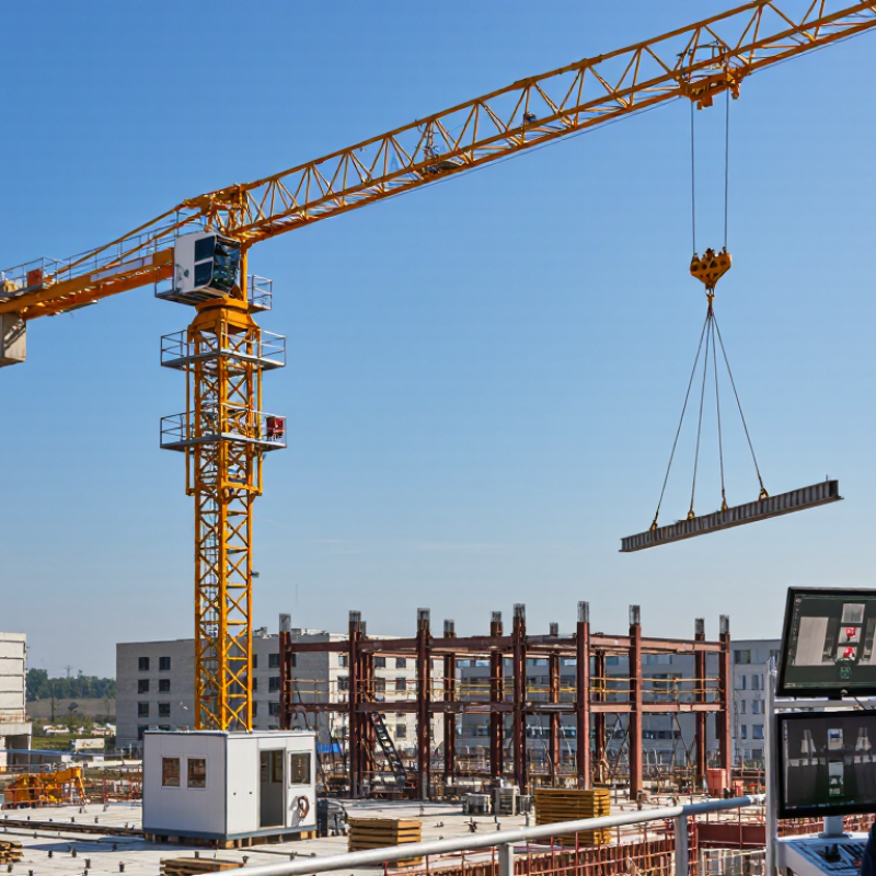
| Remote Operator Console |
Control Interface |
Provides the operator with controls, status information, alarms, and camera views without requiring the operator to sit in the crane cab. |
Usually includes joysticks, push buttons, emergency-stop controls, displays, and adjustable seating or standing controls. |
Converts operator commands into secure control signals for crane movement and displays feedback from onboard systems. |
| Wireless Communication Link |
Communication |
Transfers control commands and operating data between the remote console and the crane. |
Commonly uses a dedicated industrial wireless network; actual range depends on site layout, antenna placement, interference, and network design. |
Requires reliable, low-latency communication. A loss of communication should trigger a controlled stop or safe-state response. |
| Main Control Cabinet |
Automation and Electrical Control |
Processes commands, monitors sensors, and coordinates motors, brakes, limit switches, and safety devices. |
Typically contains a programmable logic controller, motor drives, relays, circuit protection, and safety-rated control components. |
Acts as the crane’s central decision-making system and prevents commands that conflict with configured operating limits. |
| Electric Motors and Variable-Frequency Drives |
Drive System |
Power hoisting, trolley travel, and slewing movements. |
Motor capacity varies by crane size and duty class; variable-frequency drives provide controlled acceleration, deceleration, and speed adjustment. |
Allow precise remote movement and smoother positioning while reducing shock loads caused by abrupt starts and stops. |
| Hoisting Mechanism |
Load Handling |
Raises and lowers the load through a drum, wire rope, sheaves, hook block, and braking system. |
Rated capacity depends on the crane configuration and radius. Lifting speed is normally selectable to support both rapid travel and precise placement. |
Receives remote hoist commands while load limits, upper and lower travel limits, and brake status are continuously monitored. |
| Trolley and Trolley Drive |
Horizontal Load Movement |
Moves the trolley and suspended load along the jib. |
Travel speed and allowable radius depend on the crane design, load chart, and operating mode. |
Enables the operator to position loads accurately from a remote station, often with camera assistance at the hook area. |
| Slewing Mechanism |
Rotation System |
Rotates the upper structure of the tower crane around its vertical axis. |
Uses one or more slewing motors, gearboxes, and brakes; speed is controlled to limit swinging and improve positioning. |
Remote controls regulate rotational direction and speed, while programmed limits can restrict movement in congested or restricted areas. |
| Tower Mast and Sections |
Structural Support |
Supports the crane’s upper structure and transfers loads to the foundation or climbing system. |
Built from bolted steel sections; height is determined by the number of mast sections, site conditions, and required working reach. |
Normally does not move during operation, but its structural condition and connection status are essential to safe remote operation. |
| Jib and Counter-Jib |
Structural and Load Distribution |
The jib provides load reach, while the counter-jib supports machinery and counterweights to balance the crane. |
Jib length and maximum capacity vary by configuration; capacity generally decreases as the working radius increases. |
Remote operation relies on the crane’s programmed load chart to prevent commands that exceed the permitted capacity at a selected radius. |
| Load Moment and Overload Limiter |
Safety System |
Monitors load, radius, and calculated load moment to help prevent overload conditions. |
Uses load and position measurements to compare operating conditions with the crane’s rated load chart. |
Warns the operator and may restrict or stop hazardous movements when a configured limit is reached. |
| Limit Switches and Position Sensors |
Position and Travel Safety |
Detects the position or end of travel for the hook, trolley, slewing system, and other moving parts. |
Includes upper and lower hoist limits, trolley end limits, and optional slew-zone or anti-collision sensors. |
Provides feedback to the control system and helps prevent travel beyond safe mechanical or programmed boundaries. |
| Cameras and Operator Displays |
Remote Visibility |
Shows the hook, load, landing zone, travel path, and surrounding work area. |
May include fixed, pan-tilt-zoom, or load-view cameras; performance depends on lighting, weather, mounting position, and network quality. |
Extends the operator’s visual awareness when the crane is controlled from the ground or a separate control room. |
| Anti-Collision and Zone-Control System |
Site Safety |
Helps manage interference between cranes, structures, exclusion zones, and restricted work areas. |
Uses position data, configured virtual boundaries, and site-specific operating rules. |
Can issue warnings or limit selected movements before the crane enters a prohibited or occupied zone. |
| Emergency-Stop Circuit |
Emergency Safety |
Stops hazardous crane movements when an emergency is detected. |
Emergency-stop devices are typically available at the remote console and on or near the crane, depending on the installation. |
Removes movement commands and places the relevant control circuits into a defined safe condition. |
| Brakes and Load-Holding Devices |
Mechanical Safety |
Stops and holds the hoist, trolley, and slewing movements when commands are released or power is interrupted. |
Electromagnetic or spring-applied brakes are commonly used, with brake capacity matched to the drive and rated load. |
Supports fail-safe stopping and helps keep a suspended load or moving mechanism under control during communication or power faults. |
| Power Supply and Backup Protection |
Power and Protection |
Supplies electrical power to the crane, control cabinet, drives, sensors, and communication equipment. |
Industrial three-phase power is common; voltage and frequency depend on the local electrical installation and crane design. |
Power monitoring can identify phase loss, undervoltage, overcurrent, or other faults that could affect remote control reliability. |
| Wind-Speed Sensor |
Environmental Monitoring |
Measures wind conditions at or near the crane’s upper structure. |
Configured warning and shutdown thresholds depend on the crane manufacturer’s instructions, load condition, and applicable regulations. |
Provides automatic warnings or movement restrictions when wind conditions exceed the permitted operating limits. |
| Data Logger and Diagnostic System |
Monitoring and Maintenance |
Records operating events, alarms, faults, load information, and maintenance-related data. |
May store event histories locally or transmit approved data to a supervisory system. |
Helps supervisors review remote operations, identify recurring faults, and schedule inspections or maintenance. |
 Dazheng Crane